Tensile properties are composed of the reaction of the materials to resist when forces are applied in tension. Determining the tensile properties is crucial because it provides information about the modulus of elasticity, elastic limit, elongation, proportional limit, reduction in area, tensile strength, yield point, yield strength, and other tensile properties. Tensile properties vary from material to material and are determined through tensile testing, which produces a load versus elongation curve, which is then converted into a stress versus strain curve. Tensile properties are usually determined through tensile testing, which is normally described by an ASTM standard test. The appropriate standards for tensile testing are ASTM D638 and ASTM D3039, depending on the type of polymer composite. ASTM D638 is recommended for randomly oriented, discontinuous, moldable, or low reinforcement–volume composites. Instead, ASTM D3039 is applied for highly oriented and/or high tensile modulus fiber-reinforced polymer composites. Specimens for tensile testing are usually dumbbell or dog bone haped and rectangular bar-shaped.
Tensile properties show how the material will react to forces being applied in tension. Tensile tests are able to show the ability of a material to withstand tensile loads without failure. They can also measure the ability of a material to deform under tensile stresses. Tensile tests of polymers are used to determine the tensile strength, tensile modulus, tensile strain, and elongation at yield, or at break. These properties are important to determine if the material is suited for specific applications or if it will fail under specific stresses.
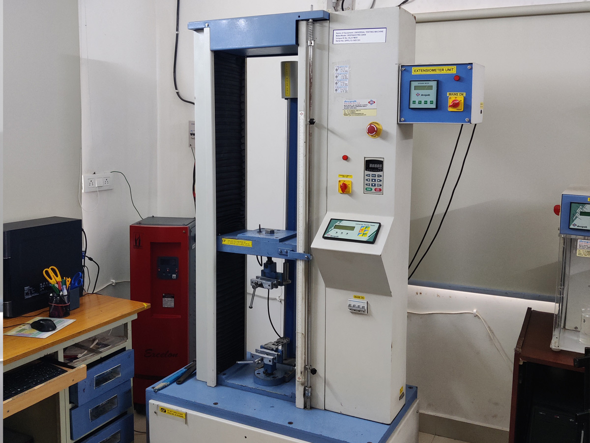
Instruments used: We use UTM for testing this property.
Flexural strength, also known as modulus of rupture, or bend strength, or transverse rupture … If we don’t take into account defects of any kind, it is clear that the material will fail under a bending force which is smaller than the corresponding.
Flexural stress, on the other hand, exerts both tensile and compressive force upon an object. … Whereas, when the extreme fibers are defective, then tensile strengthis lower than the flexural strength. Importance of Flexural Strength. Calculation offlexural strength is considered crucial in structural mechanic n mechanics, the flexural modulus or bending modulus is an intensive property that is computed as the ratio of stress to strain in flexural deformation, or the tendency for a material to resist bending.
Stiffer would mean the material deflects less under a given load. The flexural modulus is inversely related to deflection – a lower deflection would result in a higher modulus. So a higher flexural modulus material is ‘stiffer’ than a lower flexural modulus material.
Flexural strength, also known as modulus of rupture, or bend strength, or transverse rupture strength is a material property, defined as the stress in a material just before it yields in a flexure test. … The flexural strength represents the highest stress experienced within the material at its moment of yield.
The most common purpose of a flexure test is to measure flexural strength and flexural modulus. Flexural strength is defined as the maximum stress at the outermost fiber on either the compression or tension side of the specimen. Flexural modulus is calculated from the slope of the stress vs. strain deflection curve.
What are the differences between flexural and tensile strength? … Flexural Strength is the capacity of the concrete (usually beams) to resist deformation under bending moment. It is sometimes called Bending Strength. Tensile Strength is the capacity of concrete to resist tension/stretched tight.
The flexural modulus is represented by the slope of the initial straight line portion of the stress- strain curve and is calculated by dividing the change in stress by the corresponding change in strain (Fig. 2.43). The procedure for calculating flexural modulus is similar to that for tensile modulus calculations.
Instrument used: We use UTM for testing this property.
Tear resistance is the measurement of a sample’s ability to resist tearing. Tear resistance can be impacted considerably by the speed of the test, e.g. test speed used in generate the tear. Tear propagation resistance for the purpose of acceptance testing is common with materials such as paper and rubber.
Tear Strength or Tear Resistance. Tear Strength or Tear Resistance of rubber is defined as the maximum force required to tear a test specimen in a direction normal to (perpendicular to) the direction of the stress. … Some are cut (nicked) to provide a starting point for tearing, while others are not.
Instrument used: We use UTM for testing this propert.
The interlaminar shear strength (ILSS) characteristic describes the shear strength between the laminate planes.
Purpose of the Test: The interlaminar shear strength of laminates with a brittle matrix, for example, those made of epoxy resin, is typically determined using a short beam shear test (SBS). It makes use of the fact that shear stresses always occur in a flexure test. If the span is small in comparison to the specimen thickness, the shear stresses that occur in comparison to the normal stresses generated by the bending moment are very large. In this way, shear stress can be generated in brittle matrix materials, which enables measurement of the shear strength.
The shear strength of the matrix material or the quality of the fiber-matrix bonding can be characterized depending on the break type.
This test method is relatively simple to employ and requires a simple tool that has good alignment options and precise centering of the die. For this reason, the method is often used in quality control and is suitable for comparing materials.
However, the method determines only in-plane shear properties, since compressive stress peaks usually arise near the upper anvil and can influence the measured results. Testing of Standard Laminates
In materials development, standard laminates with a thickness of 2 mm are tested. Depending on the standard used, the span is 8 or 10 mm and must be set to an accuracy of up to ±0.1 mm. EN 2563 defines a very small tolerance of ±0.02 mm for the flexure tup.
ZwickRoell’s test tools simplify the tasks of specimen centering and setting the span, as well as precise parallel alignment of the supports.
Testing of Laminates Made of Finished Structures
Laminates made of profiles, plates, or components often have other thicknesses. In these cases, it is important that the relationship of the span to the laminate thickness is observed. The span must be able to be set accurately for each test series with minimum effort and the centering should have to be adjusted only once. ZwickRoell’s ILSS test fixture is equipped with a counter lead screw for this purpose. The supports can be set to the required span in observance of the mid- point. Defined gage lengths on the sides of the supports make it possible to accurately measure the span.
This test is for Composite materials and the layered structures.
Instruments used: We use UTM for testing this property.
In essence, bearing strength is the maximum stress load that the unit can “bear” or hold before the structure fails. This parameter necessary for composite materials in construction industry.
Instruments used: We use UTM for testing Ultimate Load Bearing Strength.
Compressive properties describe the behavior of a material when it is subjected to a compressive load. Loading is at a relatively low and uniform rate. Compressive strength and modulus are two common values generated by the test.
The specimen is placed between compressive plates parallel to the surface. The specimen is then compressed at a uniform rate. The maximum load is recorded along with stress-strain data. An extensometer attached to the front of the fixture is used to determine modulus.
SPECIMEN SIZE:
Specimens can either be blocks or cylinders. For ASTM, the typical blocks are 12.7 x 12.7 x 25.4mm (½ by ½ by 1 in). and the cylinders are 12.7mm (½ in) in diameter and 25.4mm (1 in) long. For ISO, the preferred specimens are 50 x 10 x 4mm for modulus and 10 x 10 x 4mm for strength.
Instrument used: We use UTM for testing Compression strength.
SPECIMEN SIZE
Specimens can either be blocks or cylinders. For ASTM, the typical blocks are 12.7 x 12.7 x 25.4mm (½ by ½ by 1 in). and the cylinders are 12.7mm (½ in) in diameter and 25.4mm (1 in) long. For ISO, the preferred specimens are 50 x 10 x 4mm for modulus and 10 x 10 x 4mm for strength.
Instrument used: We use UTM for testing Compression strength.
Creep is a time-dependent deformation of a viscoelastic material under the application of a constant stress at a constant temperature. Relaxation is the counterpart of creep, namely, a time- dependent stress of a viscoelastic material under the application of a constant deformation at a constant temperature
Instrument used: We use UTM for testing Creep and relaxation.
Izod impact test is a common test to understand notch sensitivity in plastics.Notched Izod Impact is a single point test that measures a materials resistance to impact from a swinging pendulum. Izod impact is defined as the kinetic energy needed to initiate fracture and continue the fracture until the specimen is broken. Izod specimens are notched to prevent deformation of the specimen upon impact. This test can be used as a quick and easy quality control check to determine if a material meets specific impact properties or to compare materials for general toughness.
The specimen is clamped into the pendulum impact test fixture with the notched side facing the striking edge of the pendulum. The pendulum is released and allowed to strike through the specimen. If breakage does not occur, a heavier hammer is used until failure occurs. Since many materials (especially thermoplastics) exhibit lower impact strength at reduced temperatures, it is sometimes appropriate to test materials at temperatures that simulate the intended end use environment.
The specimens are conditioned at the specified temperature in a freezer until they reach equilibrium. The specimens are quickly removed, one at a time, from the freezer and impacted. Neither ASTM nor ISO specify a conditioning time or elapsed time from freezer to impact – typical values from other specifications are 6 hours of conditioning and 5 seconds from freezer to-impact.
The standard specimen for ASTM is 64 x 12.7 x 3.2 mm (2½ x ½ x 1/8 inch). The most common specimen thickness is 3.2 mm (0.125 inch), but the preferred thickness is 6.4 mm (0.25 inch) because it is not as likely to bend or crush. ASTM impact energy is expressed in J/m or ft-lb/in. Impact strength is calculated by dividing impact energy in J (or ft-lb) by the thickness of the specimen. The test result is typically the average of 5 specimens.
Instrument used: Izod & Charpy Impact tester.
Dynamic Mechanical Analysis (DMA) is a technique that is widely used to characterize a material’s properties as a function of temperature, time, frequency, stress, atmosphere or a combination of these parameters. The DMA, dynamic mechanical analyzer is one of the most flexible, cost-effective instruments available today. With a fully rotational sample compartment and accessories you can test samples by simulating real world scenarios easily and effectively
What is DMA? A Dynamic Mechanical Analysis, otherwise known as DMA, is a technique where a small deformation is applied to a sample in a cyclic manner. This allows the materials response to stress, temperature, frequency and other values to be studied. The term is also used to refer to the analyzer that performs the test. DMA is also called DMTA for Dynamic Mechanical Thermal Analysis.
What does DMA measure? A DMA measures stiffness and damping, these are reported as modulus and tan delta. Because we are applying a sinusoidal force, we can express the modulus as an in-phase component, the storage modulus, and an out of phase component, the loss modulus. The storage modulus, either E’ or G’, is the measure of the sample’s elastic behavior. The ratio of the loss to the storage is the tan delta and is often called damping. It is a measure of the energy dissipation of a material. A While Young’s modulus, which is calculated from the slope of the initial part of a stress-strain curve, is similar conceptually to the storage modulus, they are not the same. Just as shear, bulk and compressive moduli for a material will differ, Young’s modulus will not have the same value as the storage modulus. It is a measure of how well a material can get rid of energy and is reported as the tangent of the phase angle. It tells us how good a material will be at absorbing energy. It varies with the state of the material, its temperature, and with the frequency. The relationship of the applied sinusoidal stress to strain is shown, with the resultant phase lag and deformation A Modulus values change with temperature and transitions in materials can be seen as changes in the E’ or tan delta curves. This includes not only the glass transition and the melt, but also other transitions that occur in the glassy or rubbery plateau. These transitions indicate subtler changes in the material. rates. A properly calibrated instrument requires calibration for both temperature and force. A well prepared specimen should be of even thickness with parallel sides and right angle. Assuming the correct choice of geometry for the sample, a deformation of 50 microns and heating rates of 2-3 ˚C/minute normally work fine. 6 Q How do I know what geometry to use? A The choice of the geometry you run your sample in is dictated by the sample’s physical state at the beginning of the experiment, its difficulty in loading, and the experiment you want to run. For example, a stiff bar of polymer can be run in all of the flexure fixtures, but single cantilever is often used because it is simple to load and allows thermal expansion of the specimen. Uncured thermosets are often run in shear.
Materials tested: We can do DMA analysis on plastics,Rubbers, Cmposites and ceramics from – 150C to 400C.